 |
Head-on shot of #113303. Notice that the CH-113 `Labrador' has the
solid nose panels.
For the modeller: note the rotors, matt black, both side with a black leading edge extending onto the yellow tip (hubs are gloss black); the position of the two 'holes', on either side (cooling of the electronics, I believe); the plan-view shape of the nose radome (not circular) and the double retractable landing lights. Also note the additional black `dashed' lines on the canopy framing. This isn't the norm, but rather this was the only airframe so marked, that I had seen. One can also notice the angle & approximate location of th HF `towel rack,' on the port side. For some reason, the `Labrador' has it located higher on the fuselage. Photo by: Scott Hemsley |
 |
Starboard profile of CH-113 `Labrador' #113303. Note the shape of the
fin/APU.
Photo by: Scott Hemsley |
 |
Port view of #113303. Note the profile shape of the nose radome and
the relatively high location of the HF `towel rack.' Other detail
features will be noted in subsequent photos.
Photo by: Scott Hemsley |
 |
Head-on shot of the aft-end of #113303. Note the walkways on the
sponsons, the protruding exhausts and the APU exhaust. The trailing
edge of the fin is offset to starboard, thus giving an asymmetrical
appearance to the APU.
Photo by: Scott Hemsley |
 |
A rear, 3/4 port view.
Things to note: the HF `towel rack'; `Top Hat' screens over the engine intakes; the blade antenna under the cockpit side transparency (both sides); the braces for the aux. tanks (aerodynamic cross section for the 'Lab' & circular cross-sections, on the `Voyageur' and the the three covers over electrical(?) connections - above the lowered ramp (on both sides) These covers only appear on the 'Labrador'. Corresponding connections on the `Voyageur' are left uncovered. As well, on most kits of the Boeing 107, there is a small screen, located just behind the port side `eyebrow' window, just above the lightning flash. This doesn't appear on either the `Lab' nor the `Voyageur.' Typically, on the port side, the blistered window arrangement (from the front) is window #1, #2 and #4. Starboard, the blister arrangement is on window #1 and #2. This also applies to the `Voyageur.' Photo by: Scott Hemsley |
 |
This applies to both the `Lab' and the `Voyageur.' If the rear ramp
is lowered, a flat `wind-deflection' panel is also lowered. This is
located in such a way, that when closed, it overlays the ramp hinge.
This view is from the front. I apologize for the overall darkness of
the photo. Even though flash was used in the hanger, it seemed to be
`absorbed.'
The small white `posts', in the photo, are the base attachment points for the 6 whip antenna used for the location of Emergency Crash Transmitter, signals. Photo by: Scott Hemsley |
 |
Same deflection panel, seen in photo #6, but from
the rear. Note it's proximity to the ramp hinge line. The starboard sponson
is in the foreground and a white UHF blade antenna, is seen in the shadows.
Another hanger oriented photo.
Photo by: Scott Hemsley |
  |
Close-up of the externally mounted Crash Location Transmitter (CLT),
located on the starboard side, below the exhaust. Applicable to all
CH-113's. The CLT is designed to `pop' free upon impact and
automatically emit a signal that will be picked up by SAR units.
Note: two views are show at left each offering a different enhancement, to show different detail. Photo by: Scott Hemsley |
 |
Close-up of the rear rotor housing. The light is located on both
sides, in identical positions, Again, this is common to all CH-113's.
Note the gloss black rotor hubs and the matt black rotor blades. Also,
one can begin to see the extent of the panel lines, especially when it
concerns the `clamshell' doors, providing maintenance access. These are
not the best fit.
Photo by: Scott Hemsley |
 |
Rear starboard view of a CH-113 Labrador, showing upper sponson
detail. Note the walkway, and the `flat' aerodynamic braces for the
tanks. In the foreground, is one of the electrical covers, previously
mentioned. Also visible, is one of the few `kick-in' foot holds.
Photo by: Scott Hemsley |
 |
Same Labrador, same hanger! Fuel dump detail. Applicable to all CH-113's. Photo by: Scott Hemsley |
 |
Side shot of a pair of the `Top Hat' intake screens (so called
because of their appearance). These were removed for maintenance. Of
note to the modeller, the base of each is fitted to the contours of
either the port or starboard intake, thus these screens are not
interchangeable between sides!
Photo By: Scott Hemsley |
 |
Front shots of the `Top Hats.'
Photo by: Scott Hemsley |
 |
Those `Top Hats,' belong to this `Lab.' Although another dark hanger
shot (honest, I did use flash!), details to note are: the shape of the
intake openings (less screens); part of the transmission is visible in
the intake opening on the leading edge of the rear rotor housing and the
visible seam created by the `fit' of the `clamshell' access doors.
There are three fasteners for these doors, two of which are visible in the shot, located above and below the large `intake' opening. The CH-113 has two red anti-collision beacons on the rotor housing, located on the top of the housing, fore and aft of the `base plate' for the rotor hub. The aft beacon, is centered on the top of the housing while the forward beacon, is offset, centered on the top of the port-side `clamshell door.' Applies to all CH-113's. Photo from the collection of Scott Hemsley |
 |
Along the spine, looking Forward. Note the port walkway; the two
large blade antenna; GPS (Global Positioning) antenna - that small white
square; the wiring associated with the external winch and the `vertical
seam,' created by the fit of the forward housing `clamshell' doors.
Photo from the collection of Scott Hemsley |
 |
Aft shot (from the spine) of the front rotor housing. Note the
fitting of the various panels; the walkways and the connection points of
the wiring for the winch.
Photo from the collection of Scott Hemsley |
 |
Like the previous photo, the front rotor housing, only this time
showing the small port walkway and a bit more of the `clamshell doors.'
Photo from the collection of Scott Hemsley |
 |
Another shot of the forward rotor housing. This time, the top.
Noteworthy is the panel lines resulting from the fit of the `clamshell'
doors,the two fasteners and rotor hub detail. Also visible is the large
'outlet' in the foreground, and the pitot tube on the starboard side,
just above the `eyelet' window of the cockpit side glazing.
Photo from the collection of Scott Hemsley |
 |
Winch detail. Also note the opened rotor housing and how it also will
double as a maintenance platform for the attending `Airframe Techs.'
Photo by: Scott Hemsley |
 |
Pitot tube close-up.
Photo by: Scott Hemsley |
 |
Mustn't forget the small exhaust on the starboard side of the forward
rotor housing!
Photo by: Scott Hemsley |
 |
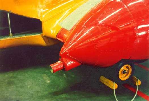
Head-on nose detail. Things of note are the double retractable landing
lights; interior details like the base of the foot pedal mechanisms and
the heating/de-fogging vents; the angle of the blade antenna located
under the side cockpit glazing and the large offset blade antenna. You
can also see two of the six (arranged in equally-spaced pairs) whip
antenna previously mentioned. Also visible is a smaller, centrally
mounted blade antenna as well as the forward post for the `closeline'
antenna on the starboard side. Only the Labrador features this antenna.
The mounting bracket for the ``Nightsun'' spotlight can also be seen. The
bracket is always fitted, but the spotlight, itself, is only fitted for
night operations.
CAF flight crews also utilize NVG, but only for flying on night SAR's and then, only by one of the cockpit flight crew. They do have their use for tricky maneuvers such as hovering above tree-top or setting down in confined areas, but they do have their shortcomings, like a lack of depth-perception. That's why the policy of only one flight crew member using the NVG's at any one time. Note the sign in the foreground warning of ``Explosives.'' This particular Labrador was in the hanger, readied for immediate SAR scramble, fully `armed' with flares (all pyrotechnics are regarded as ``explosives''). Photo by: Scott Hemsley |
 |
Close-up of the double landing lights and ``Nightsun'' mounting
bracket.
Photo by: Scott Hemsley |
 |
Rear shot of those landing lights and their respective wells.
Photo by: Scott Hemsley |
 |
For the modeller who insists on leaving the forward crew door open.
Detail of the door's interior, looking forward.
Photo by: Scott Hemsley |
 |
More door interior, this time looking aft.
Photo by: Scott Hemsley |
 |
Starting a series of interior views. Flight Engineer's jump seat,
in the stowed position (on the right-hand wall of the cockpit
access-way. The F/E is also the winch operator, when on station.
Of note, is a portion of the cockpit `blackout' curtain, for night SAR's. Quite often the cabin lights will be on for the SARTECH's attending the search victims.note the flashlight on the wall. The yellow bar is a brace for the opened door in the event of a water pickup. Photo by: Scott Hemsley |
 |
Instrument panel of a CH-113 Labrador. Also note the foot pedals and
the International Orange seat covers.
Photo by: Scott Hemsley |
 |
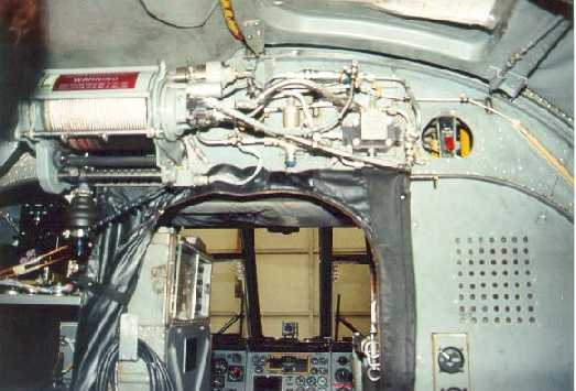
The large `box' on the left side of the cockpit access-way contains
circuit breakers and internal communications circuits. The stowed cable
is the link for the F/E, in his duties as winch operator (leaning out
the crew door), with the flight crew. The other end plugs into the
cockpit wall just behind the pilot's seat. Note the `step' from the rear
cabin into the cockpit is more of a ramp, with a single step.
Photo by: Scott Hemsley |
 |
If you chose to open the forward crew door....
... the `black box' storage rack. Also note portions of cabin soundproofing, the F/E's safety harness (for winch operations) and a stowed `blackout curtain.' Photo by: Scott Hemsley |
 |
..... upper section of the wall directly opposite that opened crew
door. Note items such as the fire extinguisher, interior of the smaller
emergency exit, first aid kit, internal winch (still fitted above the
cockpit access-way), cabin soundproofing.....
Photo by: Scott Hemsley |
 |
...... (cont'd from the previous photo) `coffee pots'. better view
of the smaller emergency exit and the stowed life raft.
Photo by: Scott Hemsley |
 |
This structure is the same item the coffee pots (previous photo)
were on. only this is the view from the other side, looking forward.
Those pouches will contain anything from maps to loose equipment. The
seat cushion in the foreground is for the port observer during a search.
This position is marked by the forward blister on each side.
Photo by: Scott Hemsley |
 |
The observer's position starboard side, also at the forward blister.
The photo is looking aft.
Photo by: Scott Hemsley |
 |
Internal winch detail. Still fitted and mounted above the cockpit
access-way. Prior to the fitting of the external winch, this was used
to winch personnel either off the rear ramp or the belly hatch.
Currently, it's just a back-up to the external mounted winch.
Photo by: Scott Hemsley |
 |
If you open the rear ramp, just a taste of the busy cabin interior.
Looking forward, you have four stretcher (mounted on the port cabin
wall, in pairs) and opposite, locker/bench seats. Immediately forward
of these, are the observer seats. Note the cabin soundproofing, the
equipment stowed under the lower stretchers, the "Stoke's stretcher"
full of equipment (stowed above the bench seats), and forward of that,
is another, smaller, overhead stowage. The shoulder harnesses are
movable, looped over a 'hefty rod', running the length of the cabin, on
both sides. This allows some seating flexibility according to the
mission cabin layout.
The personnel in the photo are my squadron `escort' and another ``Buzz'' member. Photo by: Scott Hemsley |
 |
Another view of the cabin interior looking forward. The cabin
soundproofing start were the bench seating starts. Aft of that, you
have the bare airframe.
Photo by: Scott Hemsley |
 |
I know this is actually a CH-113(A) `Voyageur' (notice the extra
glazing on the nose, the lower HF positioning, larger aux.tanks... but
all that will come later..).
This was included to illustrate those 'clamshell' doors I kept referring to. This crew just returned from a SAR, lasting several days and prior to bringing it into the hanger, are giving it a `once over.' Also notice the droop of the rotors. Photo by: Scott Hemsley |